Build a No-Fuss Particle Detector
There’s nothing like particle physics to make you aware that we exist in an endless three-dimensional pinball game. All around us, subatomic particles arc, collide, and barrel along with merry abandon. Some originate within our own bodies, others come from the far ends of the cosmos. But detecting this invisible tumult requires equipment, which can be costly. I wanted to create a way to detect at least some of the pinballs for less than US $15.
My main reason was to have a new teaching tool. I’m doing a Ph.D. in the Physics Institute III B at RWTH Aachen University, and I realized such a detector would help satisfy my teaching obligations while tapping into my interests in physics, electronics, and software design.
Fortunately, I didn’t have to start from scratch. Oliver Keller at CERN’s S’Cool Lab has created a DIY particle detector that relies on inexpensive silicon photodiodes to detect alpha and beta particles (helium nuclei and free electrons whizzing through the air, respectively) and estimate their energy. Normally, photodiodes are used to respond to light, such as the signals used in fiber-optic communications. But a charged particle striking the photodiode will also produce a pulse of current, with higher-energy particles generating bigger pulses. In practice, given typical conditions and the sensitivity of the photodiodes, this primarily means detecting beta particles.
In Keller’s design, these pulses are amplified, converted to voltages, and transmitted via a cable from an audio jack on the detector to the microphone input of a laptop or smartphone. The data is then digitized and recorded.
A colleague of mine had built the CERN device, but I realized there was room for improvement. Passing the analog pulse signal through the length of an audio cable left the detector prone to noise from various sources. In addition, the design requires its own power source, in the form of a 9-volt battery. Apart from the hassle of having a separate battery, this also means that if you miswire the device, you’ll send an unacceptable voltage into an expensive smartphone!
Reducing Amplification Noise
I decided I would solve these problems by bringing the digitization to the photodiodes. The closer I could get it, the less noise I’d have to contend with. Noise-resistant digitized data could then be sent via a USB connection, which could also supply power to the detector.
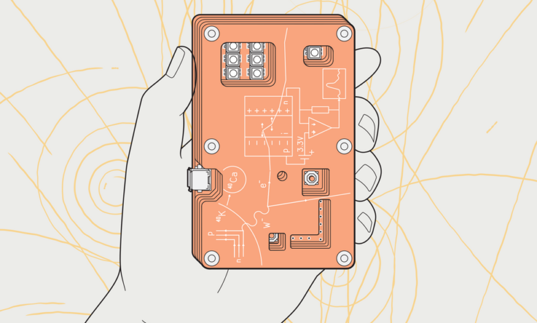
The BetaBoard uses three types of printed circuit board: The cover [top] and a body board [middle] have no circuit traces and are used to create a light-tight and electromagnetically shielded enclosure; the bottom board hosts a photodiode detector array and an RP2040 microcontroller. James Provost
Of course, to digitize the signal from the photodiodes, I would need some onboard processing power. I settled on the RP2040 microcontroller. Although it does have some known problems with its analog-to-digital converter, you can work around them, and the chip has more than enough compute power as well as a built-in USB controller.
In my first design of my so-called BetaBoard, I created a single printed circuit board populated with the RP2040, an array of photodiodes, and a set of low-noise amplifier integrated circuits. I wrapped the board in aluminum tape to prevent light from triggering the photo detectors. The results proved the concept, but while I’d eliminated the noise from the audio cable, I discovered I’d introduced a new source of noise: the USB power supply.
Higher-frequency noise—over 1 kilohertz—from the USB connection comes from data and polling signals flowing over the interface. Lower-frequency noise originates in the AC power supply for the host computer—50 hertz here in Europe. I filtered out the high-frequency noise by inserting a low-pass RC filter before the amplifiers’ supply voltage pins and liberally using capacitors in the rest of the circuitry. Filtering out the 50-Hz noise in hardware is tricky, so my solution was to just integrate a digital high-pass filter into the software I wrote for the RP2040. (Hardware and software files are available from my Github repository.)
The software also provides a serial interface to the outside world: A human or a program can send commands via the USB cable and get data back. I wrote a Python script to record data and generate visualizations.
Another improvement I made to my initial design was to eliminate the need to wrap the board in aluminum tape (or place it in a container, as in Keller’s original version).
To do that, I designed two other types of PCB with the same external dimensions as the original board, but without any circuitry. The first type has two large cutouts: an open area over the photodiode array and amplifiers, and another area over the RP2040 and its supporting circuitry. The photodiode cutout is surrounded by a broad metal fill on the back and front of the PCB, with the fills connected by vias. By stacking two of this type of PCB on the circuit board containing the components, I created an enclosure that provides shielding against electromagnetic interference.
A photodiode has a junction between positively and negatively doped regions, with a neutral depletion layer forming in between. Incoming light or charged particles [red line] creates charge carriers in the depletion region. This produces a spike in current between the doped regions. The height of the spike is proportional to the energy of the particle.James Provost
The second type of PCB acts as a cover for the stack, with a smaller cutout over the photodiode array, over which I placed some black tape—enough to block light but still allow beta particles to reach the photodiodes.
The result is a robust detector, albeit not the most sensitive in the world. I estimate that where a research-grade detector would register 100 counts per second from a given beta emitter, I’m getting about 10. But you can do meaningful measurements with it. My next step is to give it the ability to detect alpha particles as well as beta particles, as Keller’s version can do. I could do this now by modifying a $10 photodiode, but I’m experimenting with ways to use the cheaper photodiodes used in the rest of the design. I’m also working on the documentation so that it can be used in classroom settings that don’t have the luxury of having the detector designer present!
IEEE Spectrum